Godot Isn't Just for Games: A Live Joystick Dashboard
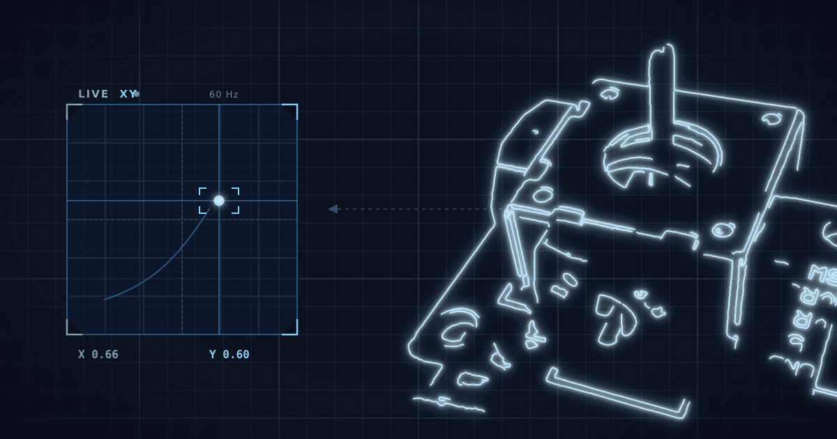
In part one, a button in a Godot 4 scene reached down a USB cable — through a small Python-to-UDP bridge, because Godot doesn't speak serial — and lit an LED on an Arduino. That proved the round trip. This post makes data flow the other way: a 2-axis joystick streaming its position up the same wire into a Godot console, a glowing dot tracking the stick across an XY pad in real time, with the LED button still doing its thing. A dashboard that only writes is a light switch; one that reads and writes is a control panel.
You'll need the setup from part one working — LED on D13, bridge running, Godot project open. The additions here: one joystick module, nine wires, a sketch that streams, and a script that draws.
Same spirit as part one: this is written by someone exploring these two technologies, not a hardware veteran. The wiring you'll see is simply what worked on the bench, arrived at by experiment — there are almost certainly tidier or more optimized ways to lay out the circuit. Take it as a working starting point you can improve on, not the last word.
The code. The joystick sketch, the shared bridge, and the full Godot project are in the open blog-code repo — clone it or download the ZIP.
The 30-second version
- Same bridge, new direction. Part one's Python bridge already relays both ways; now the Arduino → Godot lane carries
"x,y,btn"lines and Godot reads them withPacketPeerUDPin_process. - One module, three values. The KY-023 joystick gives you X, Y, and a click — three signals from a single module.
- Rate-limit at the source — the sketch sends at ~60 Hz, plenty for a human-facing display without flooding the port.
- Frame your data. Multi-value telemetry is where partial lines start to hurt — parse complete newline-terminated lines only, never fragments.
- Smooth in the engine. Raw ADC readings jitter; a frame-rate-independent lerp on both axes keeps the dot gliding instead of twitching.
- The same architecture scales — if you want somewhere to take it next, swap the Arduino for a flight controller speaking MAVLink and this becomes a drone ground-control station.
What you add
Really just one new part on top of part one's shopping list — plus a handful more of the jumper wires you already have:
- 2-axis analog joystick module (KY-023) — X, Y, and a built-in click, all in one part. ~$2.
- Nine jumper wires. The KY-023's header points sideways, so it can't seat in the breadboard — it lives beside the board on five female-to-male leads, and four male-to-male jumpers carry its signals from the board on to the Uno. Its ground reuses part one's existing GND wire, so it needs none of its own. Not a new purchase; part one's kit ships a fistful of both.
That's the whole delta: no extra resistor (the KY-023's button rides the Arduino's internal pull-up), no new power, no second breadboard. Like everything else in this build, both are in the ELEGOO UNO R3 Super Starter Kit — if your Uno came in a kit, you almost certainly already own them.
The hardware: nine wires
The LED stays exactly where part one put it — D13 through a 220Ω resistor into the LED, and the LED's short leg back to GND at row 15. Nothing about that loop changes; you're adding a joystick beside a circuit that already works. The point of a dashboard is a live value you can feel, and a 2-axis stick gives you three at once — X, Y, and a click — from a single module.
So start on the board you already built. The KY-023's pin header points sideways, so — unlike the LED — it can't seat in the breadboard itself; it lives beside the board on a five-lead ribbon. Each lead lands in its own row on the far side of the same breadboard; from there, four short jumpers carry its signals back to the Arduino, and its ground ties into the ground the LED is already using:
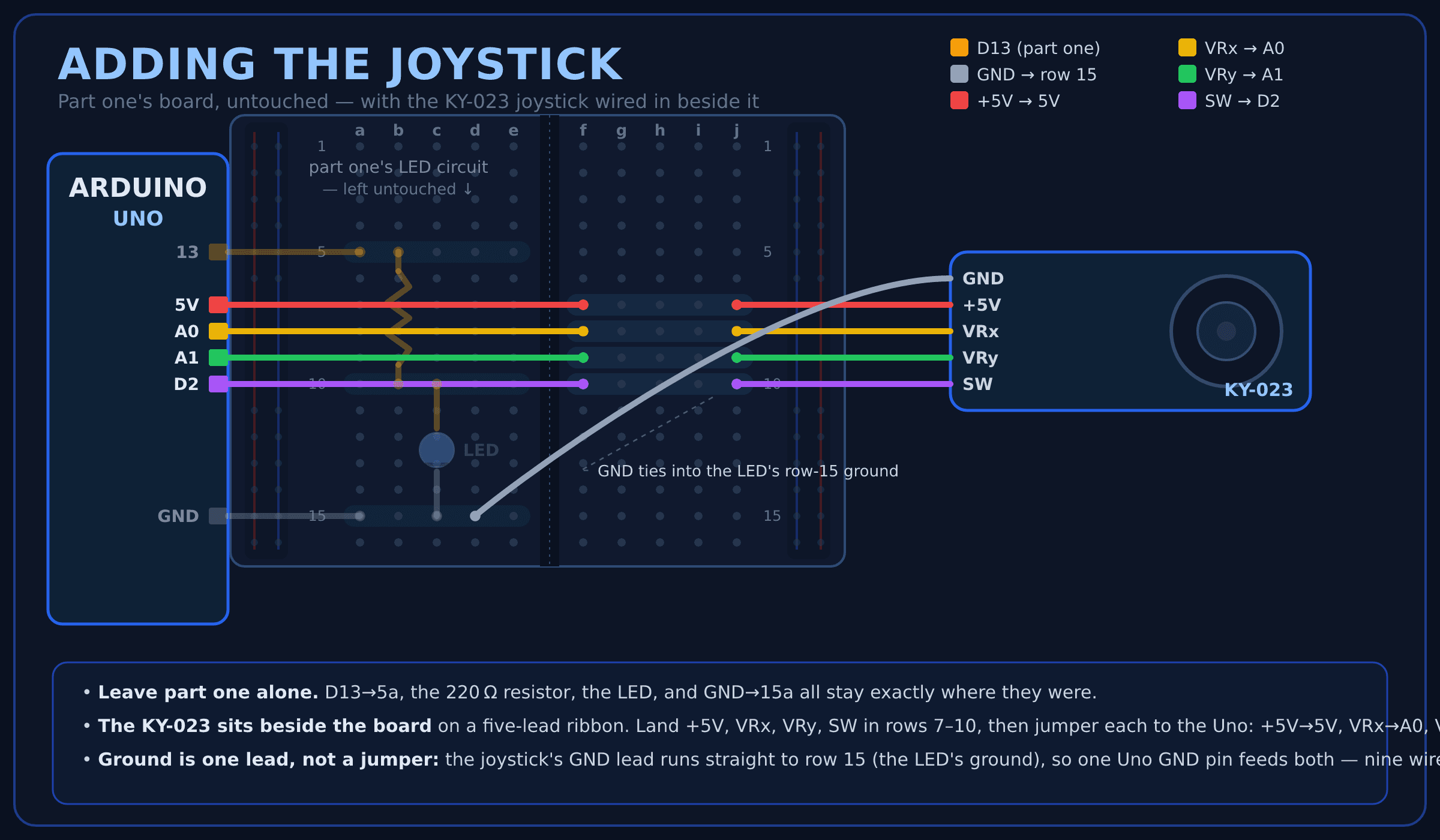
The idea to internalize is the same one part one leaned on: a breadboard row — the five holes a–e, or f–j on the far side — is a single wire. Plug the KY-023's four signal-and-power leads into four rows on the f–j side (rows 7–10 in the diagram) in the order its pins actually come — +5V, VRx, VRy, SW from top to bottom — so each lands in its own row. Then drop a jumper into each row's open f-hole and run it to the matching Arduino pin — +5V→5V, VRx→A0, VRy→A1, SW→D2. That's eight wires so far — four leads plus four jumpers — and ground makes nine.
That leaves ground, and here's where you actually tie into the existing circuit. Don't run a second ground wire back to the Uno. The LED already has a ground on the board — its short leg sits in row 15, jumpered once to the Uno's GND. So run the joystick's GND straight into that same row 15, and it's grounded through the wire part one already put there: one jumper, one Uno GND pin for the whole board. That's the real payoff of "a row is a single wire" — row 15 is ground now, so anything you plug into it is grounded too.
Prefer a flat checklist to a board layout? Here's the same wiring summarized by Arduino pin — LED and joystick together — so you can check your work at a glance:
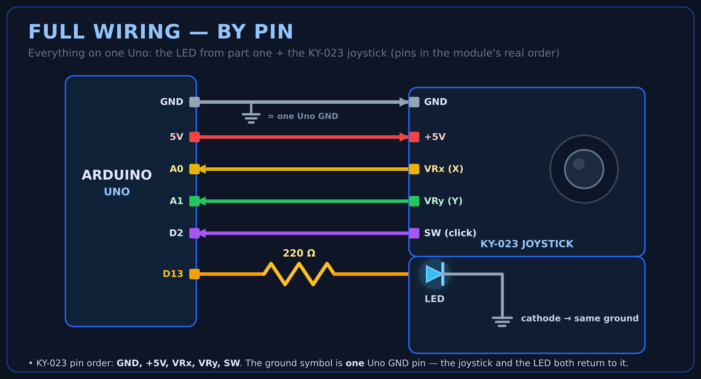
Two components total, a few minutes of breadboarding, no soldering — you're only adding wires to an already-proven pipe.
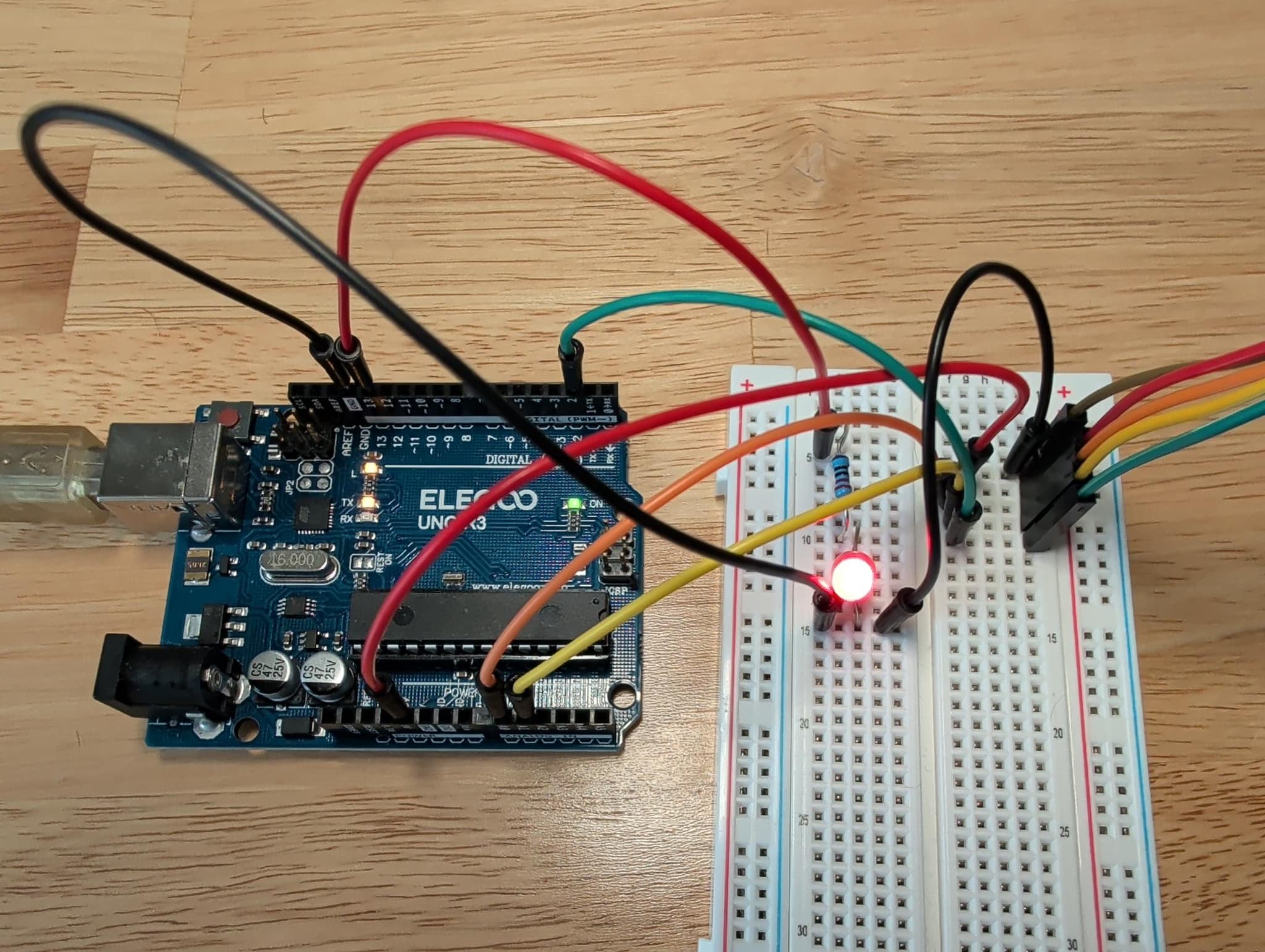
And here it is on the actual bench — the KY-023 wired in beside the LED loop from part one, the red LED still lit:
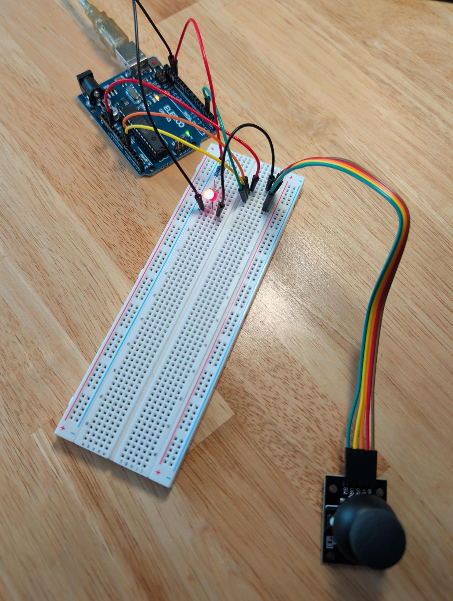
And a closer look at the wiring — the same rows and jumpers the diagrams above lay out:
The Arduino side: telemetry out, commands in
This sketch replaces part one's. Commands in stay the same (L1/L0 still drive the LED); what's new is the outbound half — newline-delimited CSV at a fixed rate. SEND_INTERVAL_MS = 16 gives ~60 Hz, which keeps the dot feeling glued to the stick and is still far less than the port can carry at 115200 baud.
// JoystickBridge.ino — stream "x,y,btn" telemetry out; still obey "L1"/"L0" in.

const int VRX_PIN = A0;   // joystick X axis
const int VRY_PIN = A1;   // joystick Y axis
const int SW_PIN  = 2;    // stick push-button (active LOW)
const int LED_PIN = 13;   // LED Godot controls (also the Uno's onboard LED)

const unsigned long SEND_INTERVAL_MS = 16;  // ~60 Hz
unsigned long lastSend = 0;

void setup() {
  Serial.begin(115200);
  pinMode(SW_PIN, INPUT_PULLUP);
  pinMode(LED_PIN, OUTPUT);
}

void loop() {
  // Telemetry out, rate-limited: "512,498,1\n"
  unsigned long now = millis();
  if (now - lastSend >= SEND_INTERVAL_MS) {
    lastSend = now;
    int x = analogRead(VRX_PIN);            // 0-1023
    int y = analogRead(VRY_PIN);            // 0-1023
    int btn = (digitalRead(SW_PIN) == LOW); // 1 = pressed
    Serial.print(x);
    Serial.print(',');
    Serial.print(y);
    Serial.print(',');
    Serial.println(btn);
  }

  // Commands in: two-byte "L1" / "L0"
  while (Serial.available() >= 2) {
    char c = Serial.read();
    if (c == 'L') {
      char v = Serial.read();
      digitalWrite(LED_PIN, v == '1' ? HIGH : LOW);
    }
  }
}
The bridge: nothing to change
Same bridge from part one, still running — it forwards whole lines in either direction, so nothing about it changes.
But one thing it quietly does starts mattering now: partial-line reassembly. The OS delivers serial data in arbitrary chunks — "51" now, "2,498,1\n10" later — so the bridge buffers until it sees a newline and only ever forwards complete lines. With part one's two-byte commands you could get away without this; with multi-value telemetry you can't. Skip it and Godot occasionally parses "2" as an axis value and the dot teleports.
The Godot side: an XY pad with a tracking dot
Part one's scene grows up: a Control scene styled as a dark, neon-blue console titled GODOT + ARDUINO DEMO — a Panel serving as an XY pad (with a faint crosshair drawn through its center), a glowing ColorRect dot inside it, and the LED toggle button from part one below. One script, and the outbound half is unchanged: set_dest_address(), not connect_to_host() — the gotcha part one spells out. The new half is the inbound socket: PacketPeerUDP is polled in _process; we drain every packet that arrived since last frame and keep the newest, parse the three values, smooth the position as a Vector2, and map it into the pad — inverting Y so pushing the stick up moves the dot up, because ADC-up and screen-up disagree. The stick's built-in click recolors the dot from cyan to green, which turns out to read faster than any status label. The full project — this scene, its script, and the sketch — lives in the blog-code repo; open godot/ArduinoGodot/ in Godot 4 to run it as-is.
# Main.gd — attached to Main.tscn; reads x,y,btn telemetry and drives the XY pad.

extends Control

const TELEMETRY_PORT := 4242
const COMMAND_ADDR := "127.0.0.1"
const COMMAND_PORT := 4243
const ADC_MAX := 1023.0
const SMOOTH_SPEED := 12.0

const COLOR_IDLE := Color(0.3, 0.7, 1.0)     # cyan
const COLOR_PRESSED := Color(0.2, 1.0, 0.4)  # green

@onready var pad: Panel = $Panel/Pad
@onready var dot: ColorRect = $Panel/Pad/Dot
@onready var led_button: Button = $Panel/LedButton

var _udp_in := PacketPeerUDP.new()
var _udp_out := PacketPeerUDP.new()
var _target := Vector2(512, 512)   # rest near center so the dot starts middle
var _smoothed := Vector2(512, 512)
var _btn := false
var _led_on := false

func _ready() -> void:
    _udp_in.bind(TELEMETRY_PORT, "127.0.0.1")
    # To SEND with PacketPeerUDP in Godot 4, use set_dest_address — NOT
    # connect_to_host, which is for receiving and silently drops outbound packets.
    _udp_out.set_dest_address(COMMAND_ADDR, COMMAND_PORT)
    led_button.pressed.connect(_on_led_pressed)

func _process(delta: float) -> void:
    # Drain the queue; the newest packet wins. Format: "x,y,btn" e.g. "512,498,1"
    while _udp_in.get_available_packet_count() > 0:
        var parts := _udp_in.get_packet().get_string_from_utf8().split(",")
        if parts.size() >= 3 and parts[0].is_valid_int() and parts[1].is_valid_int():
            _target = Vector2(float(parts[0]), float(parts[1]))
            _btn = parts[2].strip_edges() == "1"

    # Frame-rate-independent smoothing so the dot glides instead of twitching.
    _smoothed = _smoothed.lerp(_target, 1.0 - exp(-SMOOTH_SPEED * delta))

    # Normalize raw ADC (0..1023) to 0..1, then place the dot in the pad.
    # Invert Y so pushing the stick up moves the dot up.
    var n := (_smoothed / ADC_MAX).clamp(Vector2.ZERO, Vector2.ONE)
    var travel := pad.size - dot.size
    dot.position = Vector2(n.x * travel.x, (1.0 - n.y) * travel.y)

    # The stick's push-button recolors the dot.
    dot.color = COLOR_PRESSED if _btn else COLOR_IDLE

func _on_led_pressed() -> void:
    _led_on = not _led_on
    _udp_out.put_packet(("L1" if _led_on else "L0").to_utf8_buffer())
    led_button.text = "LED: ON" if _led_on else "LED: OFF"
Run the sketch, run the bridge, hit play in Godot. Nudge the stick and the dot glides across the pad, smooth and immediate; press the stick straight down and it flips cyan to green. The LED button from part one still works, and that's the wow: the moment data flows both ways through the same wire, this stops being a light switch and becomes a control panel — and everything from here to a full ground station is just more of the same.
Here's that running on the bench — a short clip of the dot chasing the joystick in real time, with the stick's click flipping its color.
From there it's Godot all the way up: push the theming further with a Theme resource, draw a richer crosshair or a fading position trail via _draw(), tween a warning flash when the stick pins an axis. The engine parts are the fun parts, and they're standard Godot.
Framing, jitter, and flooding: the boring stuff that bites
Everything from part one's gotcha list still applies — baud mismatch, one owner per COM port, the Windows UDP reset, connect_to_host() — but telemetry brings its own set, and every one of these will get you exactly once:
- Partial lines. Covered above, repeated here because it's the #1 "values randomly spike" bug. Buffer until newline, always.
- Flooding. Print as fast as
loop()runs and you'll saturate the port and buffer up seconds of latency. Rate-limit at the source; 30–60 Hz is the useful range for anything a human watches. - ADC jitter.
analogReadwobbles a few counts even with your hand off the stick. Smooth it — the exponential lerp in the Godot script above, or average a few samples on the Arduino. Never wire a raw reading straight to the screen. - Unplugged boards. USB cables come out. The bridge catches
SerialExceptionand retries every second, so replugging just works; Godot meanwhile shows the last value — worth adding a "stale data" indicator if no packet arrives for a second or two. - Units. 0–1023 is not a unit. Normalize to 0–1, map to degrees, percent, PSI — whatever the input actually means — in one place, on the Godot side.
- Latency honesty. USB serial plus the bridge adds single-digit milliseconds — imperceptible for a dashboard, but this is not hard-real-time. Nothing safety-critical should close its control loop through this path; the microcontroller handles the fast stuff, the dashboard supervises.
- Windows blocks the bridge launcher. On Windows 11, double-clicking
start-bridge.batcan trip Smart App Control/SmartScreen with "a file that may be unsafe" — it's just an unsigned downloaded script, not a real problem. Right-click the.bat→ Properties → tick Unblock → OK, or skip the launcher and runpy bridge.pyin a terminal. (Full note in part one.)
Where this goes next: a drone ground station
That last caveat points straight at the obvious next project. The architecture above doesn't care that the thing on the other end of the link is an Arduino. Swap it for a flight controller speaking MAVLink, teach the bridge to parse MAVLink instead of CSV (pymavlink does the heavy lifting), and Godot's job barely changes — except now the packets carry attitude, altitude, GPS, and battery, and the Control nodes to build are an artificial horizon, a map, and a telemetry HUD. Same bridge pattern, same PacketPeerUDP, same smoothing tricks; the control loop stays on the flight controller where it belongs, and Godot supervises. If you've got a drone on the bench, that's the direction to take this — consider the dashboard here the flight training. (It's no accident the demo's one input is a flight stick.)
The takeaway
Godot 4 makes a genuinely good HMI tool, and the recipe is small: accept that the engine doesn't speak serial and put a small bridge in front of it, frame your data as newline-delimited lines, rate-limit at the source, smooth at the destination, and send commands back down the same pipe so the panel actually controls something. Everything else — the rendering, the layout, the animation, the single-executable deploy — is the engine doing what it already does every day for games. The surprise isn't that a game engine can do this; it's that we ever assumed it couldn't.
Need a real-time dashboard, control panel, or HMI and thinking a web stack is your only option? A game engine might be the better tool — that's exactly the kind of thing Codebycandle helps with — get in touch.
Corrections, suggestions, and topic ideas are always welcome — send them along.