Godot Isn't Just for Games: Your First Arduino Round-Trip
If you need a control panel for a piece of hardware — gauges, readouts, a couple of buttons that actually control the thing — the reflexive answer in 2026 is a web stack. Spin up a server, open a websocket, fight a charting library. But you already have a better tool installed: your game engine. A game engine is, at its core, a machine for redrawing a screen 60+ times a second in response to a stream of changing values, with a mature UI system, animation, tweening, and theming built in. That's a textbook description of an instrument panel, and the industry quietly agrees — game engines already power real HMIs, flight simulators, and digital twins. Hobbyists just rarely make the connection.
This is part one of two, and it makes the connection as small as it can possibly be: one Arduino Uno, one LED, one button in a Godot 4 scene. Click the button, and a game engine reaches down a USB cable and lights a real LED on your bench. That's the entire payoff — and it's also the entire architecture. Once this round trip works, everything in part two (coming soon) — live joystick telemetry, a glowing XY pad — is just more traffic on a wire you've already proven.
A note on who this is for: it's written for someone curious about getting Godot and Arduino talking to each other for the first time — an explorer's walkthrough of the two technologies working together, not an Arduino veteran's deep dive. If a blinking LED and a game engine in the same sentence sounds fun, you're in the right place.
The code. Every sketch, the Python bridge, and the Godot project for this build are in the open blog-code repo — clone it or download the ZIP and build along.
The 30-second version
- Godot has no native serial-port support. Don't fight it — route around it with a tiny bridge script.
- The architecture: Godot sends
L1/L0over UDP on127.0.0.1→ Python bridge (pyserial) → USB serial → Arduino toggles the pin. No compiled addon, works on Windows/macOS/Linux. - The hardware is one LED on D13 through a 220Ω resistor — and D13 is also the Uno's onboard LED, so you get a free sanity check.
- To send UDP from Godot 4, use
set_dest_address().connect_to_host()is for receiving — use it on an outbound socket and every packet silently vanishes whileput_packet()reports success. - The bridge is where the ugly stuff lives — COM-port detection, reconnects, a Windows-specific UDP crash — so Godot never has to know any of it happened.
- This is part one of two. Part two — coming soon — sends data the other way: a joystick streaming live telemetry into Godot, a glowing dot chasing the stick in real time. Worth checking back for.
What you'll need
The whole demo is a few dollars of parts plus a board. If you're starting from nothing, don't buy these piecemeal — a starter kit is cheaper than the sum of its parts and comes with the breadboard and jumper wires you'd otherwise forget.
- Arduino Uno R3 — the microcontroller. ~$28 genuine, ~$15 for an ELEGOO-compatible board.
- Breadboard + jumper wires — solderless wiring. ~$5–10.
- LED — the output Godot controls. A few cents.
- 220Ω resistor — limits current through the LED. A few cents.
- USB cable (A-to-B) — board power and serial. ~$5, usually boxed with the board.
No joystick yet — that arrives in part two. Every one of these — board included — is in the ELEGOO UNO R3 Super Starter Kit (~$43, and often cheaper), which is the kit this build is based on. There's a smaller basic kit around $20 if you want the shortest shopping list. If you already own an Uno, you almost certainly have the LED and resistor in whatever kit it came in.
Why a game engine is the right tool
Consider what a live control panel actually needs: a render loop that redraws every frame regardless of whether anything "happened" (Godot's _process), a retained-mode UI toolkit with layout containers, progress bars, and buttons (Control nodes), cheap smooth animation for needles and fades (Tween, lerp), and a theming system so the whole panel can look like a cockpit instead of a settings dialog (Godot's Theme resources). Every one of those is a solved, first-class problem in a game engine — and an ongoing chore in a browser.
There's also the deployment story. A Godot panel exports to a single executable. No node_modules, no local server, no browser chrome around your gauges. Double-click, fullscreen, done. For kiosk-style panels and bench tools, that's not a small thing.
The one thing Godot conspicuously lacks is the ability to open a serial port. That's the honest gap in this whole idea, so let's deal with it first.
The architecture: a bridge, because Godot doesn't speak serial
There is no SerialPort class in Godot. Community GDExtension addons exist that read the COM port directly inside the engine, and they work — but they're compiled, per-platform dependencies that you get to rebuild or re-fetch every time Godot or your OS updates. For a bench tool, keeping the engine stock is the saner default.
The alternative costs about forty lines: a bridge script that owns the serial port and forwards each line over UDP to localhost, in both directions. Today only one direction carries anything — Godot's commands going down to the board — but the bridge is symmetric from day one, which is exactly why part two costs so little.
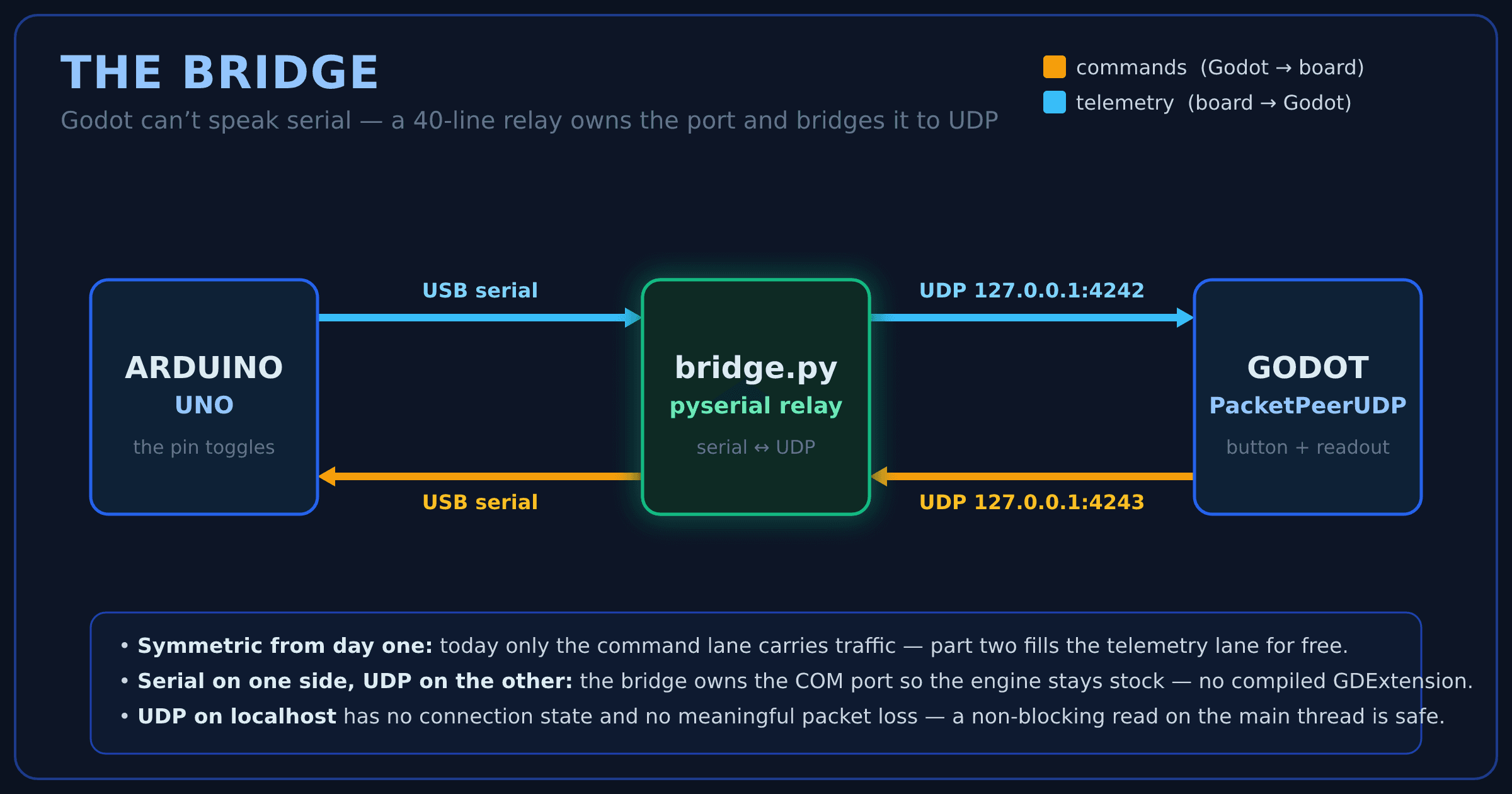
Why UDP and not TCP? On localhost, packet loss is a non-issue, there's no connection state to manage, and a non-blocking UDP read or write on the main thread is completely safe. This is exactly the workload UDP was made for.
pip install pyserial, run it, leave it running. It auto-detects the board, reassembles newline-framed lines from whatever chunks the OS hands it, and reconnects if the cable comes out.
# bridge.py — serial <-> UDP relay for the Godot dashboard
import socket, time
import serial
from serial.tools import list_ports

BAUD = 115200                       # must match the sketch
GODOT_ADDR = ("127.0.0.1", 4242)    # telemetry -> Godot
LISTEN_ADDR = ("127.0.0.1", 4243)   # commands <- Godot

def find_port():
    for p in list_ports.comports():
        desc = p.description or ""
        if "Arduino" in desc or "CH340" in desc or "USB Serial" in desc:
            return p.device          # e.g. "COM4" on Windows
    return None

sock = socket.socket(socket.AF_INET, socket.SOCK_DGRAM)
sock.bind(LISTEN_ADDR)
sock.setblocking(False)

while True:
    port = find_port()
    if not port:
        time.sleep(1.0)
        continue
    try:
        with serial.Serial(port, BAUD, timeout=0) as ser:
            print(f"connected: {port}")
            buf = b""
            while True:
                buf += ser.read(256)          # non-blocking
                while b"\n" in buf:           # only forward complete lines
                    line, buf = buf.split(b"\n", 1)
                    sock.sendto(line.strip(), GODOT_ADDR)
                try:
                    cmd, _ = sock.recvfrom(64)
                    ser.write(cmd)            # Godot -> board
                except BlockingIOError:
                    pass                      # no command waiting
                except ConnectionResetError:
                    pass                      # Windows: Godot not listening yet
                time.sleep(0.005)
    except serial.SerialException:
        print("port lost, retrying...")
        time.sleep(1.0)
Two details in there are doing quiet, load-bearing work. The line-buffering: the OS delivers serial data in arbitrary chunks, so the bridge buffers until it sees a newline and only ever forwards complete lines. Today's traffic is short enough that you'd rarely notice the difference — but the moment part two starts streaming multi-value telemetry, this is the line between clean data and values that randomly spike.
The second except is the one that will surprise you, and it's Windows-specific. When the bridge sends a packet to Godot's port and nothing is listening yet — because you started the bridge before pressing Play — Windows bounces back an ICMP "port unreachable," and that makes the next recvfrom on the same socket raise ConnectionResetError (WinError 10054) and kill the bridge. It's a long-standing UDP-on-Windows quirk, not a bug in your code. You'll see the textbook fix elsewhere — a sock.ioctl(socket.SIO_UDP_CONNRESET, False) call — but that constant isn't exposed in every Python build, so the portable move is to simply catch the error and move on.
One heads-up before you open the download: the snippet above is the teaching cut — the whole relay in about forty lines, so you can see it at a glance. The bridge.py in the code download is that same relay hardened for daily use — --port/--baud overrides, broader board auto-detection, a pause for the Uno's reset-on-connect, command validation, and a keep-the-window-open error prompt — so it's noticeably longer than what's printed here. Read this version to understand the idea; run that one.
The hardware: one LED
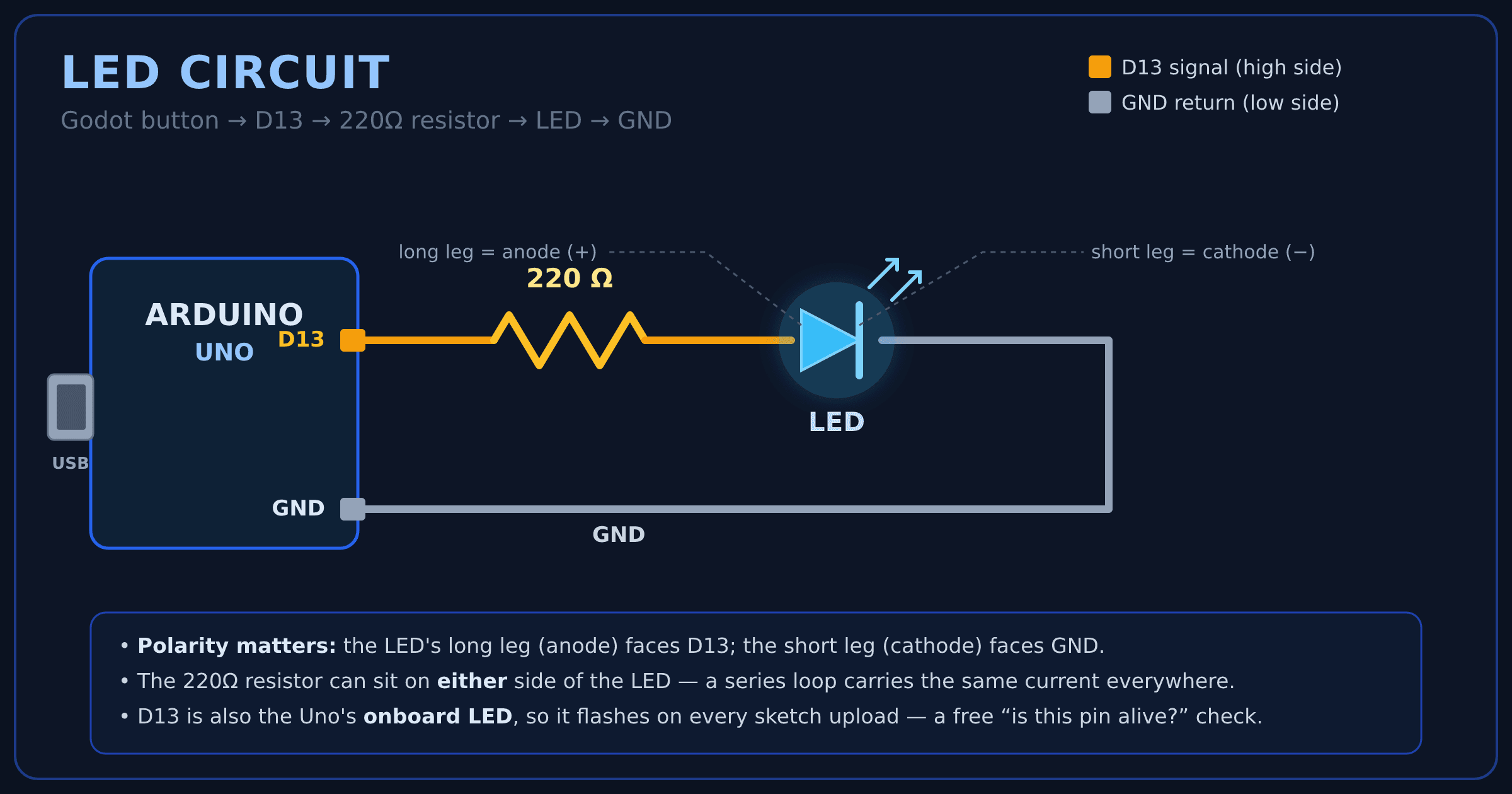
One component, one resistor, two minutes of breadboarding, no soldering:
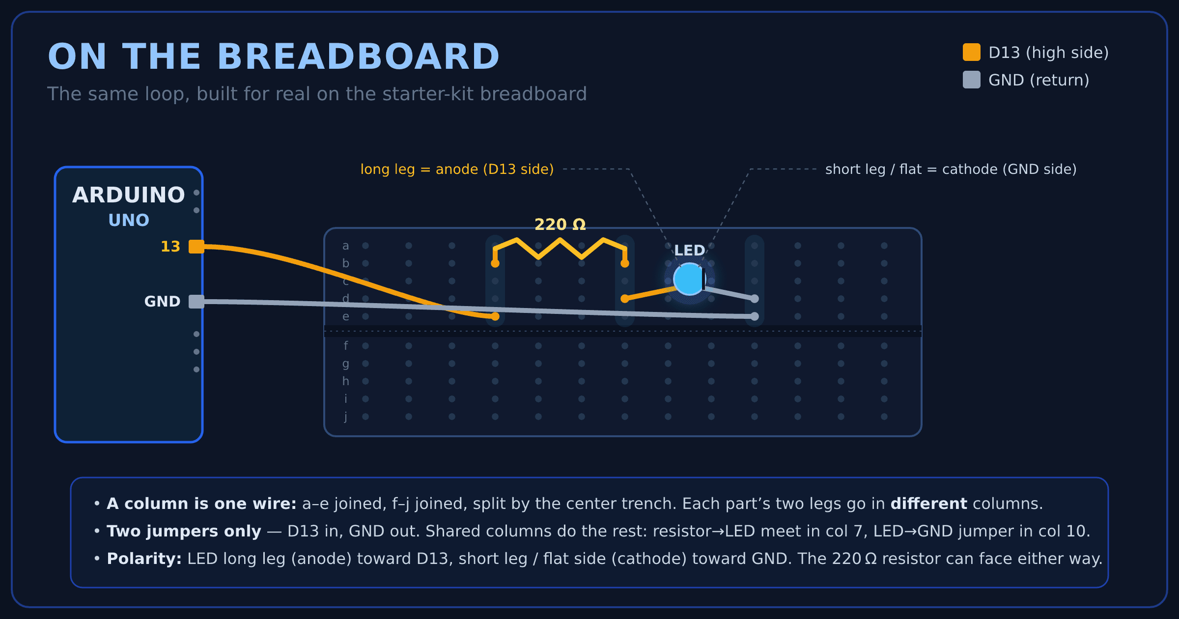
Following along on real hardware? Here's the exact same loop as a physical build — every part and both jumpers from the starter kit, plugged into the breadboard. The one idea to internalize: within a block, the five holes in each numbered row (a–e) are wired together, so dropping the resistor's leg and the LED's leg into the same row connects them with no extra wire. Only two jumpers touch the Arduino — D13 into 5a, GND out of 15a — and the shared rows do the rest.
And here's that exact circuit lit on the bench:
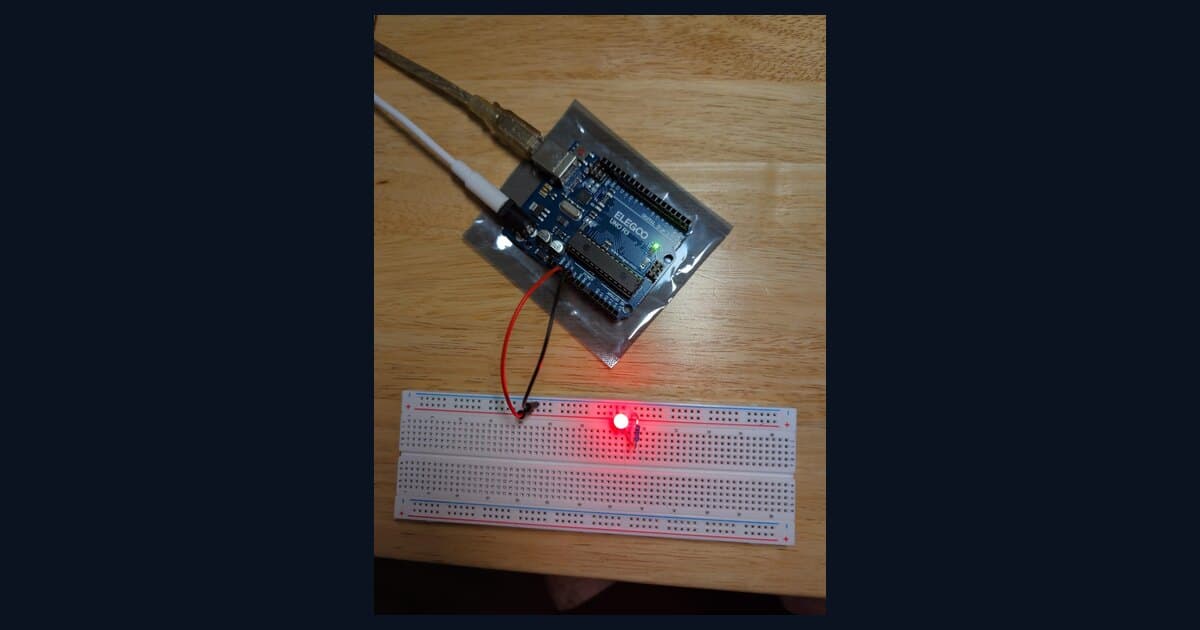
This is the real wiring, not a shortcut: the red jumper carries D13, the black one is the GND return, and the whole board runs on the USB cable alone — no separate power supply. The LED you see lit is exactly one Godot click away from going dark.
No breadboard handy? The Uno's onboard LED is already wired to D13, and the sketch drives it too. Watch the LED's polarity: the long leg (anode) goes toward D13, the short leg toward GND, and the resistor can sit on either side of it — a series loop carries the same current everywhere. D13 doubling as the onboard LED has a bonus side effect: it visibly flashes during every sketch upload, a free "is this pin alive" sanity check before you've wired anything at all.
The Arduino side: commands in
The sketch does one thing: read newline-terminated commands off the serial port and obey. L1 means on, L0 means off. The buffer-and-parse shape looks like overkill for a two-byte command, but it's the same shape every serial protocol you'll ever write settles into — accumulate until the line ends, act on complete lines only, drop anything malformed.
// LedBasics.ino — read "L1"/"L0" from serial (via the bridge) and toggle the LED.

const uint8_t PIN_LED = 13;   // LED via 220 ohm resistor (also the onboard LED)

char cmdBuf[8];
uint8_t cmdLen = 0;

void setup() {
  Serial.begin(115200);
  pinMode(PIN_LED, OUTPUT);
  digitalWrite(PIN_LED, LOW);
}

void loop() {
  // Commands in from Godot: "L1" / "L0", one per line.
  while (Serial.available() > 0) {
    char c = Serial.read();
    if (c == '\n' || c == '\r') {
      if (cmdLen >= 2 && cmdBuf[0] == 'L') {
        digitalWrite(PIN_LED, cmdBuf[1] == '1' ? HIGH : LOW);
      }
      cmdLen = 0;
    } else if (cmdLen < sizeof(cmdBuf) - 1) {
      cmdBuf[cmdLen++] = c;
    } else {
      cmdLen = 0;  // overflow guard: drop the runt line
    }
  }
}
The Godot side: one button
A Control scene (LedBasics.tscn) styled as a dark, neon-blue panel titled GODOT + ARDUINO: LED, with a single styled toggle button. One script, one socket, no polling loop — the button's pressed signal does all the work. One line deserves special attention before you copy it: outbound packets use set_dest_address(), not connect_to_host() — the difference is subtle enough to cost you an evening, and it gets its own bullet below.
# LedBasics.gd — attached to LedBasics.tscn; sends L1/L0 over UDP on button press.

extends Control

const COMMAND_ADDR := "127.0.0.1"
const COMMAND_PORT := 4243

@onready var led_button: Button = $Panel/LedButton

var _udp_out := PacketPeerUDP.new()
var _led_on := false

func _ready() -> void:
    # To SEND with PacketPeerUDP in Godot 4, use set_dest_address — NOT
    # connect_to_host, which is for receiving and silently drops outbound packets.
    _udp_out.set_dest_address(COMMAND_ADDR, COMMAND_PORT)
    led_button.pressed.connect(_on_led_pressed)

func _on_led_pressed() -> void:
    _led_on = not _led_on
    _udp_out.put_packet(("L1" if _led_on else "L0").to_utf8_buffer())
    led_button.text = "LED: ON" if _led_on else "LED: OFF"
Upload the sketch, run the bridge, hit Play, click the button — and an LED lights up on a physical breadboard because a game engine told it to. That's the whole architecture working end to end, with one component. It looks like a toy, but nothing about the pipe changes from here: every fancier thing you bolt on is just more lines flowing through the same bridge.
Here's that exact moment on the bench — a 45-second clip of the LED toggling from a click on the Godot button. Both the panel and the breadboard wiring in the clip are older states than what's shown above — the UI has since been restyled and the wiring tidied up — but the round trip is this build, click for click.
One quality-of-life move, since you'll start this bridge every session from here on: launch it with a double-click instead of a terminal chore. The code download ships ready-made launchers right next to the script — start-bridge.bat on Windows, start-bridge.command on macOS — that simply run bridge.py when you double-click them, no terminal required. On Windows, right-click start-bridge.bat → Send to → Desktop (create shortcut) and starting the bridge is one click from the desktop from then on. (On macOS, if the first double-click opens the file in an editor instead of running it, mark it executable once with chmod +x start-bridge.command. Rolling your own is trivial too: a one-line py bridge.py in a .bat, or python3 bridge.py in an executable shell script.) Small thing, but it turns "open a terminal, cd in, type the command" into a single click before you plug in the board.
One Windows 11 wrinkle worth flagging, because it looks alarming and isn't: the first time you launch start-bridge.bat, Smart App Control (or SmartScreen) may block it with "a file that may be unsafe." Nothing's wrong — it's an unsigned little script that arrived carrying the "downloaded from the internet" mark, and Windows is being cautious about the launcher, not about Python or the bridge. The one-click fix: right-click start-bridge.bat → Properties → tick Unblock at the bottom → OK, and it runs normally from then on. (Prefer to sidestep it entirely? Open the bridge folder, type cmd in the address bar, and run py bridge.py yourself — that's all the launcher does anyway. Avoid turning Smart App Control off just for this; that switch is a one-way door you can't easily flip back.)
Serial and sockets: the boring stuff that bites
Every one of these will get you exactly once:
- Baud mismatch. 115200 in the sketch means 115200 in the bridge. A mismatch doesn't error — it delivers garbage, which is worse.
- One owner per port. The Arduino IDE and the bridge can't both hold the COM port. Upload while the bridge is running and you get
cannot open port ... The system cannot find the file specified. Stop the bridge, upload, then restart it — always in that order. connect_to_host()does not send. The one that quietly eats real debugging time. In Godot 4,PacketPeerUDP.connect_to_host()is for receiving — but nothing stops you calling it on an outbound socket, and if you do,put_packet()cheerfully returnsOKwhile the packet never leaves the machine. The button handler logged success on every click, the bridge saw nothing, and every layer looked correct in isolation. The fix is one method name:set_dest_address(), thenput_packet(). If your commands vanish, check this first.- Windows UDP resets. Covered in the bridge section, flagged here because it's the crash you'll actually hit first. A bare
except BlockingIOErrorisn't enough on Windows — also catchConnectionResetError, or start Godot before the bridge so the port is already listening. - Windows port roulette. Boards enumerate as
COM3,COM4, whatever's free. The bridge'sfind_port()auto-detects by USB description; failing that, check Device Manager and hardcode it. - Powered hubs and dumb cables. If the board's on a USB hub, confirm the hub is actually powered — an unpowered downstream port enumerates as nothing, and
find_port()returns empty forever. Same failure mode as a charge-only cable: use a data cable, into a live port.
When one of those bites and it's not obvious where the break is — Godot, the bridge, or the wiring — bisect the round trip. The code download includes a tiny ledtest.py that fires an L1/L0 command straight at the bridge's command port, exactly like Godot does: with the bridge running, python ledtest.py L1. If the LED lights, the Arduino and bridge are fine and the fault is on Godot's side; if it stays dark, the engine is off the hook and the problem is the bridge or the wiring. One command tells you which half to debug.
Where this goes next
Right now the wire only carries commands — Godot talks, the board listens. Part two (coming soon) makes it carry live data back: a 2-axis joystick streaming x,y,btn telemetry at 60 Hz into a glowing XY pad, with smoothing, click detection, and all the framing gotchas that only show up once real data is flowing. Same bridge, same ports, same scene — a joystick you can feel. And past that, the same architecture scales to a drone ground-control station; the round trip you just built is the flight training. That full walkthrough is coming soon — check back for it, because it runs on the exact wire you just proved, so you're already halfway there.
The takeaway
The recipe for using Godot as a hardware front end is small: accept that the engine doesn't speak serial, put a forty-line bridge in front of it, frame everything as newline-delimited lines, and remember that outbound UDP means set_dest_address(). One LED is enough to prove all of it — the moment a button in a game engine lights a component on your bench, the gap between "screen" and "hardware" stops being an architecture problem and becomes a shopping list. The surprise isn't that a game engine can do this; it's that we ever assumed it couldn't.
Need a real-time dashboard, control panel, or HMI and thinking a web stack is your only option? A game engine might be the better tool — that's exactly the kind of thing Codebycandle helps with — get in touch.
Corrections, suggestions, and topic ideas are always welcome — send them along.